To generate a grid of nodes within a defined boundary:
•Click Surface > Nodes > Generate Grid; or
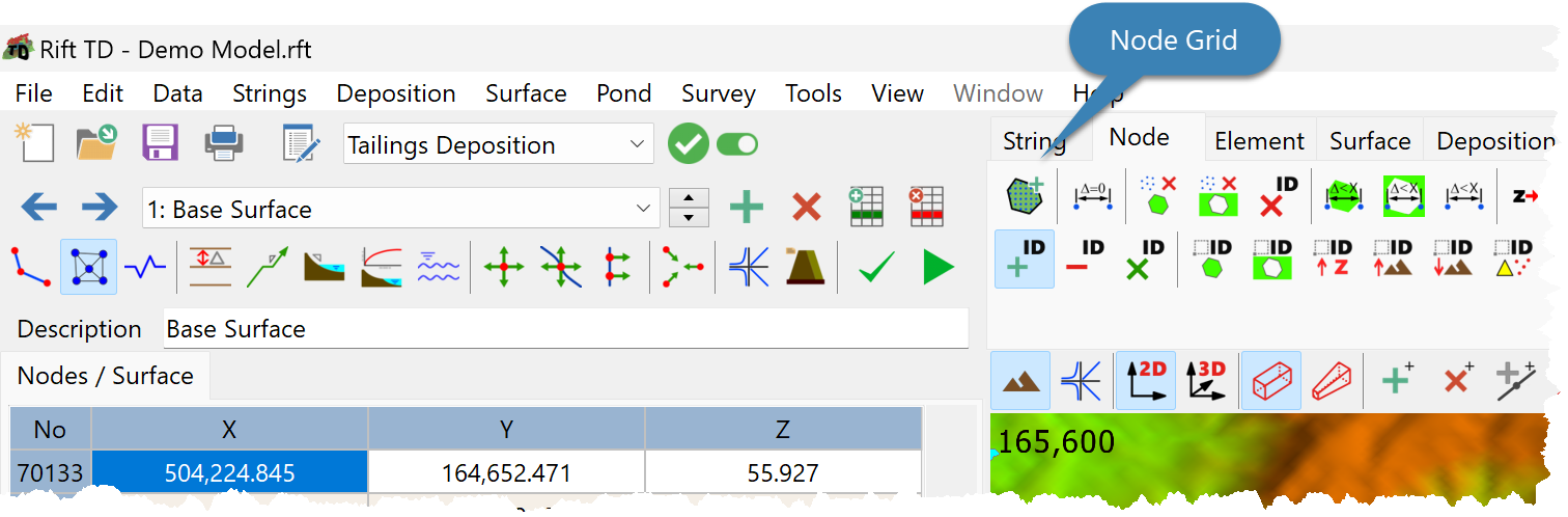
•Click the Node Node Grid Button.
•Enter Grid Parameters on the Node Grid Dialog.
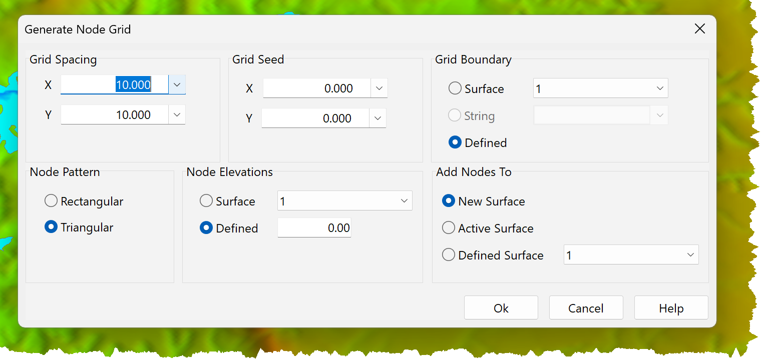
•Grid parameters comprise:
oGrid spacing: The node spacing in the x and y directions.
oGrid Seed: The coordinate for the first Node. All subsequent nodes are offset relative to Grid Seed.
oGrid Boundary: The boundary within which nodes are generated:
▪Surface: Nodes are generated within the boundary of a specified Surface.
▪String: Nodes are generated within the boundary of a specified String.
A closed String needs to be defined for this option to be enabled.
▪Defined: Nodes are generated within a User defined boundary/area.
oNode Pattern: The pattern used to generate Nodes:
▪Rectangular pattern: Nodes are generated in a rectangular pattern.
▪Triangular pattern: Nodes are generated in triangular pattern.
oNode Elevations: The elevations assigned to the Nodes:
▪Surface: Node elevations are interpolated from a Surface.
▪Defined: Node elevations are set to the specified elevation.
oAdd Nodes To: The surface that the Nodes are added to:
▪New surface: A new surface is generated and the nodes added to it.
▪Active Surface: Nodes are added to the Active Surface.
▪Defined Surface: Nodes are added to a user specified surface.
•Click OK.